The Benefits of Digital Displays in Proportional Valve Driver Systems
Introduction to Digital Displays in Proportional Valve Driver Systems
Overview of Proportional Valve Drivers
Proportional valve drivers deliver precise current control to solenoid valves in hydraulic circuits. These devices convert command signals into regulated output that adjusts spool position inside valves. Engineers rely on proportional valve driver units when applications demand smooth flow modulation rather than simple on-off operation. Modern designs incorporate pulse-width modulation to minimize heat buildup in the coil while maintaining accuracy across varying loads.
Proportional control valve driver modules often mount on DIN rail for easy integration into control cabinets. They accept analog or digital inputs and produce the exact amperage needed by each solenoid. Axiomatic and Atos both supply compact proportional valve electronics that fit standard enclosures used throughout North America. Technicians appreciate the quick replacement these DIN rail units allow during maintenance cycles on mobile equipment or factory presses.
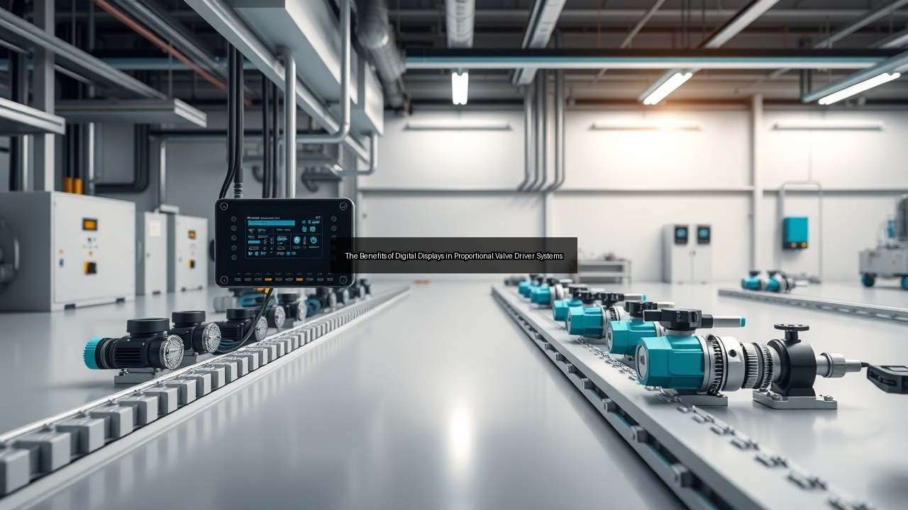
Basic proportional valve driver boards contain amplifiers that boost low-level signals to the levels required by larger coils. Some models include an H-bridge circuit for bidirectional valve operation. The addition of a digital display transforms these functional boards into operator-friendly instruments that show setpoints, actual current, and fault codes at a glance.
Importance of Digital Displays in Modern Systems
Digital displays remove guesswork from field adjustments. Operators read actual current values instead of interpreting blinking LEDs or relying on external multimeters. This clarity speeds commissioning of new hydraulic systems and reduces downtime when tuning proportional valve driver parameters on site.
Real-time feedback also supports predictive maintenance. A technician watching the display can spot rising coil resistance or voltage drops before they cause erratic valve response. Near field communication (NFC) lets engineers pull diagnostic logs onto a smartphone without opening the enclosure, further shortening service visits.
Systems that use SAE J1939 communication benefit when the display mirrors CAN bus data. The operator sees commanded versus actual values side by side, confirming that the proportional valve electronics follow the engine control module correctly. Such transparency improves overall machine performance and operator confidence.
Key Benefits of Digital Displays in Proportional Valve Systems
Enhanced User Interface for Operators
A clear digital display turns a complex proportional valve driver into an intuitive device. Operators scroll through menus to set ramp times, maximum current limits, and deadband compensation without connecting a laptop. The interface uses large numerals that remain readable even under bright sunlight on construction equipment cabs.
Four LED indicators supplement the screen to show power, communication status, and fault conditions at a distance. This combination gives both quick glances and detailed information when needed. Cart operators in material handling applications adjust flow rates on the fly through the display while the machine continues moving, eliminating the need to stop production.
Password protection built into the interface prevents unauthorized changes. Maintenance staff can still access advanced parameters via NFC or USB once they authenticate. The result is a balance between ease of use for daily operators and security for technicians.
Real-Time Monitoring and Diagnostics
Continuous current and voltage readings appear on the display so operators notice deviations immediately. When a solenoid coil begins to draw more current than expected, the proportional valve driver flags the condition before the valve sticks or overheats. This early warning prevents costly hydraulic fluid leaks or cylinder damage downstream.
Diagnostic screens list recent fault codes and operating hours. A service technician reviews this history to identify patterns such as repeated over-temperature events caused by blocked airflow around the DIN rail assembly. Data logging through the display also supports warranty claims by documenting that the proportional valve electronics stayed within rated limits.
USB ports allow export of trend files to a computer for deeper analysis. Engineers compare actual performance against design drawings and refine control algorithms accordingly. The combination of on-screen data and downloadable records accelerates troubleshooting across fleets of machines.
Improved System Responsiveness
Digital displays let operators fine-tune response curves directly at the proportional valve driver. Small changes to ramp rates or gain settings produce immediate visual feedback, allowing rapid optimization of cylinder speed and smoothness. This capability proves valuable during machine commissioning or when switching between different attachments.
Closed-loop feedback from the display confirms that commanded current reaches the coil without delay. Any lag caused by wiring resistance or amplifier saturation shows up instantly, prompting corrective action. Faster tuning cycles shorten overall project timelines in both OEM factories and field retrofits.
Operators also use the display to switch between preset profiles stored in the proportional valve electronics. One profile might prioritize precision for delicate positioning while another maximizes speed for bulk material movement. Instant profile changes keep production flowing without reprogramming.
Integration of Digital Displays with Proportional Valve Electronics
Compatibility with DIN Rail Mounts
Digital displays integrate cleanly with DIN rail mounted proportional valve driver modules. The display board snaps onto the same rail as the power stage, sharing a common backplane for signal and power connections. This layout keeps wiring short and reduces electromagnetic interference between amplifiers and sensitive analog inputs.
Standard 35 mm DIN rail spacing accommodates both the driver and its display in existing control panels. Retrofit projects in North America often replace older analog cards with these modern DIN rail assemblies because no panel modifications are required. The result is faster upgrades and lower installation costs.
Thermal design also benefits from the DIN rail format. Heat sinks on the proportional valve electronics dissipate coil current losses while the display remains at eye level for easy reading. Ventilation slots in the enclosure maintain safe operating temperatures even under continuous duty.
Utilizing USB and NFC for Connectivity
USB connections on the digital display allow direct parameter upload from a laptop or tablet. Engineers load new firmware or adjust PID constants without removing the proportional valve driver from the cabinet. This convenience speeds software updates across multiple machines on a production line.
Near field communication provides wireless access for handheld devices. A technician taps a phone against the display housing to read coil current, voltage, and temperature values. Near field communications also transfer configuration files between units, ensuring identical settings on duplicate valves without typing errors.
Both USB and NFC interfaces remain active even when the main SAE J1939 port is occupied by the vehicle bus. This dual-access approach keeps diagnostics available during normal machine operation. Security features limit NFC range and require pairing codes to prevent unauthorized tampering.
Incorporating Amplifiers and H-Bridge Circuits
The digital display works alongside integrated amplifiers that drive solenoid coils with precise current. Operators monitor amplifier output directly on screen, confirming that PWM duty cycle matches the commanded value. Any mismatch triggers an alarm before performance degrades.
H-bridge circuits inside the proportional valve electronics enable reverse polarity drive for certain valves. The display indicates direction and magnitude of current flow so technicians verify correct wiring during installation. Visual confirmation reduces the chance of reversed connections that could damage the coil.
PCB layout places the display connector near the amplifier section to minimize trace length. Short connections preserve signal integrity for fast current feedback loops. The resulting system achieves tighter control of valve spool position and smoother hydraulic response.
Impact of Digital Displays on Performance and Efficiency
Precision Control of Solenoid Valves
Digital displays enable exact current settings that translate into accurate spool positioning inside solenoid valves. Operators dial in the precise amperage needed for each flow rate rather than approximating with potentiometer adjustments alone. This precision improves repeatability across production cycles.
Feedback from the display closes the loop between command and actual coil current. The proportional valve driver corrects deviations within milliseconds, maintaining consistent cylinder velocity even as supply voltage or fluid temperature changes. Hydraulic systems therefore deliver more predictable motion profiles.
Reduced overshoot and undershoot also lower mechanical stress on valves and cylinders. Components last longer when they avoid repeated hard stops at end positions. Maintenance intervals extend and overall equipment effectiveness rises.
Voltage Regulation and Coil Management
Stable voltage regulation protects solenoid coils from over-current conditions that shorten service life. The display shows both supply voltage and regulated output so operators detect supply sags before they affect valve performance. Early detection prevents unplanned stops.
Coil temperature monitoring through the display allows automatic current reduction when limits approach. This feature keeps the proportional valve driver within safe operating margins during high ambient conditions common in mobile equipment. Coil life extends without sacrificing response speed.
Energy consumption drops because the system supplies only the current actually required. Lower average power draw reduces generator or battery load on mobile platforms. Fuel savings accumulate over thousands of operating hours across a fleet.
Reducing Error Margins with Feedback Mechanisms
Closed-loop feedback displayed in real time shrinks the gap between intended and actual valve behavior. Operators compare commanded current against measured values and adjust parameters until the two match within tight tolerances. The process eliminates much of the trial-and-error tuning common with older analog systems.
Potentiometer inputs still serve as manual overrides, yet the digital display shows their effect immediately. Technicians verify that potentiometer movement produces the expected change in coil current before releasing the machine for production. Verification builds confidence in both manual and automatic modes.
Overall system error margins shrink further when multiple proportional valve drivers share a common display bus. Centralized monitoring reveals interactions between valves that individual units might miss. Coordinated adjustments optimize the entire hydraulic circuit rather than isolated sections.
Frequently Asked Questions about Digital Displays and Proportional Valve Drivers
What are the advantages of using NFC in valve systems?
Near field communication allows quick wireless access to proportional valve driver parameters without opening enclosures. Technicians retrieve coil current, fault history, and firmware versions by tapping a phone against the display housing. This method reduces exposure to hazardous voltages and shortens service time on active machinery.
NFC also supports secure configuration transfer between identical valves. Engineers copy settings from one unit to another in seconds, eliminating manual entry mistakes. Range limits inherent to near field communications add a layer of physical security that remote wireless protocols cannot match.
Data pulled via NFC integrates with maintenance software used across North America fleets. Service records update automatically, creating an auditable trail for warranty and regulatory compliance. The combination of speed, security, and documentation raises overall maintenance efficiency.
How does a digital display improve hydraulic system performance?
A digital display provides immediate visual confirmation of current delivered to each solenoid. Operators adjust proportional valve driver settings on the spot and watch the results, achieving smoother cylinder motion and faster cycle times. Reduced oscillation around target positions improves both accuracy and throughput.
Real-time diagnostics catch issues such as voltage drops or coil degradation before they cause valve failure. Early intervention prevents unplanned downtime and protects downstream components from pressure spikes. Hydraulic systems therefore run closer to design specifications for longer periods.
Energy efficiency gains appear when operators use the display to eliminate unnecessary current overhead. Lower average power consumption reduces heat in the coil and extends component life. The net effect is higher reliability and lower operating costs across the machine lifetime.
What role does the potentiometer play in control systems?
The potentiometer supplies a manual analog reference signal to the proportional valve driver when operators need direct override capability. The digital display shows the exact current that results from potentiometer movement, allowing precise manual positioning of valves during setup or emergency situations.
Technicians compare potentiometer input against automatic commands to verify that both control paths produce consistent valve response. Any discrepancy appears instantly on screen, prompting calibration before the machine returns to production. This verification step reduces the risk of conflicting control signals.
Many installations retain the potentiometer as a backup while the primary control arrives through SAE J1939 or analog PLC outputs. The display bridges both worlds by showing which source is active and what current each demands. Operators switch between modes confidently because the interface makes the active path clear at all times.